Hello there! I'm a proud owner of an Ovation 1773 AX-4.
Despite the fact guitar is fantastic I'm very worried on not getting enough in terms of
knowledge of the relate preamp , the basically almost-hystorical OVATION OP PRO.
So .... I decided to reverse engineering IT !!!!!
In this way I will be able to correct some issues, like the well
known low volume and maybe enhance it in the next future.....
Reverse Engineering is really time consuming and tools and time are needed!!!
If You think my homework will help You a bit on loving even more Your guitar, please feel free to give a symbolic contribution for the research to my PayPal Account:
KKPRINCE
Donate
https://www.paypal.me/kkprince999
Tuesday 20 July 2100
Monday 20 July 2099
GENERAL INTERNAL LAYOUT:
The shell can be opened easily through four standard screws:
We can split the OP PRO in 2 main sections connected by a wide stripline:
1) DIGITAL SECTION & POWER SUPPLY:

2)
ANALOG SECTION + TONE CONTROLS

WELL ...now where to start ? Of course I need a Rosetta stone.......
So I will pass tons of schematics in a way to try something will match a subsection
of the OP PRO ... in a way to start the decoding!
CHEERS!
kkprince
Donate
https://www.paypal.me/kkprince999
Sunday 20 July 2098
HERE ARE THE LINKS TO THE TWO PCB HALVES OP PRO MACROS
https://www.dropbox.com/s/ne5c817d9m0l8q5/IMG_0095.JPG?dl=1
https://www.dropbox.com/s/vxzucttozkaorqf/IMG_0093.JPG?dl=1
CHEERS!
kkprince
Donate
https://www.paypal.me/kkprince999
https://www.dropbox.com/s/ne5c817d9m0l8q5/IMG_0095.JPG?dl=1
https://www.dropbox.com/s/vxzucttozkaorqf/IMG_0093.JPG?dl=1
CHEERS!
kkprince
Donate
https://www.paypal.me/kkprince999
Saturday 20 July 2097
THE ROSETTA STONE
And ...HERE IS IT.... After lot of checking I found the Rosetta Stone
Have a look at the following schema taken from an Old Op 24+ referring the Tuner Signal Shaper:

Now on the digital side of the OP PRO You can find EXACTLY the same configuration!!! BINGO.
The only value differing is the input resistor , 1 Mega instead of 220 k.

This mean I found the complete section of the circuit where the Output of the piezo goes,
once buffered (I will explain later) for being squared and directed to the Tuner IC MicroControllerUnit.
:-))
Now I can start decoding a lot of things !!!! I have to follow backward the input of this stage for searching the piezo buffer stage , probably on the other half shell of the schema!
kkprince
Donate
https://www.paypal.me/kkprince999
Friday 20 July 2096
INCREASE THE OUTPUT VOLUME ON OVATION OP PRO (Light Approach)
Time to make something GREAT on the OVATION OP PRO:
In this post I will explain how to make this unit able to OUTPUT a decent
VOLUME without crancking up the Potentiometer ALWAYS to his max and
without modify the gain of the preamp.
Let's see the 1st picture describing where the Piezo Pickup signal enters into the 1st buffer
(An operational amplifier with gain 1)(1st of four op amp on a TL064 clone IC)

The overall impedance of the Input is 1.2 MOhm ......but .....Jesus the signal is splitted in TWO by the partition network!!!!!!!!!!!!!!!!!!!!!!!! WTF?
Basically the 2 resistors cuts in two the signal , only 55% of available piezo output is used!!!!
THEN WHAT ?
VERY SIMPLE ,We maintain the overall Impadance but We change the resistors partition logic allowing to pass 90% of the signal... using a 220k + 1M Ohm resistor.
This mod is REALLY easy but You need a skilled solder guy with magnifier glasses and very small soldering iron , 10 ,15 watt...to make it good & clean:
(I am a quite good solder guy :-)
Here is the result of the mod:

OK RE-PACK all the things and switch the AMP ON.......Tuner is still working...even better...and the VOLUME??????
................MIRACLE :-)
At half of pot the volume is quite decent...... At 2 o clock is optimal ....... At 5 o clock is strong
but still absolutely no saturating the things at all.
NOW I OWN A SUPER CUSTOM OP PRO!!!!!!!!!!!!!!!!!!!
SOOOOOOOOOOOOOOOO HAPPY!!!!!!!!!!!!
:-)
KK
https://www.paypal.me/kkprince999
.
Wednesday 20 July 2095
THE MISSING DECOUPLING CAPACITOR
OK , my mod is compliant with the existing Architecture of the input buffer:
BUT....... I cannot see any decoupling capacitor separating the piezo line from the input network that is 4.5V VREF polarised........
WTF?
The 4.5 V is reaching one of the 8 pin exiting to connect the OP PRO CAN circuitry....
Not so healty or good circuit design.
4.5 volt vref is reaching the dedicated piezo pin on the socket to the CAN....
.............................................so I SUPPOSE the capacitor
to be on the CAN PCB...............more than suppose .......I HOPE SO!!!!!!!!!!!

Unfortunatly then .........I need to remove the CAN and do an ispection....searching for the capacitor.
Only other explanation for not having the capacitor is that the Piezo ground is not connected to the circuit ground but instead on the VREF virtual ground..
Let's do the inspection of the can pcb then... sigh...i need to remove it...
:-((
Donate
https://www.paypal.me/kkprince999
BUT....... I cannot see any decoupling capacitor separating the piezo line from the input network that is 4.5V VREF polarised........
WTF?
The 4.5 V is reaching one of the 8 pin exiting to connect the OP PRO CAN circuitry....
Not so healty or good circuit design.
4.5 volt vref is reaching the dedicated piezo pin on the socket to the CAN....
.............................................so I SUPPOSE the capacitor
to be on the CAN PCB...............more than suppose .......I HOPE SO!!!!!!!!!!!

Unfortunatly then .........I need to remove the CAN and do an ispection....searching for the capacitor.
Only other explanation for not having the capacitor is that the Piezo ground is not connected to the circuit ground but instead on the VREF virtual ground..
Let's do the inspection of the can pcb then... sigh...i need to remove it...
:-((
KK
https://www.paypal.me/kkprince999
Tuesday 20 July 2094
HAHAHA : Decoupling capacitor is not needed!
Yes the real schema is the following:

The Piezo is not connected to ground and the signal but between
the signal input and the VREF virtual ground !!!!!
So ....everything is OK
:-)
Wednesday 22 July 2093
Some OCP-1K Output testing
With normal strumming here We can see the average output of the Piezo:

Please note the measure is taken directly from the Piezo Jack , removed from the Preamp.
The OPC-1AK is easily outputting more than 80 mv peak to peak.
KK
Sunday 20 July 2092
Going taleban with the OP PRO Piezo Reading
Well......this is my personal way....
2.2M Impedance, 68k only resistor for Input signal....gain super good , sound is bright...

KK
Donate
https://www.paypal.me/kkprince999
2.2M Impedance, 68k only resistor for Input signal....gain super good , sound is bright...

KK
Donate
https://www.paypal.me/kkprince999
Friday 20 July 2091


Thursday 20 July 2090
TIME TO DECODE THE VOLUME CONTROL
IT will be hard.... but I have to ...for being able to even add more gain to the preamp or change the volume curve, that now is VERY prone to rapidly increase the gain when moving from (clock) position three to five....and do almost nothing from twelve to three o clock.
KK
KK
Wednesday 19 October 2089
Draft of the "post volume potentiometer" circuit
OK this is the first draft to give an idea of the signal processing after the Volume potentiometer:

Definitely this is a differential balanced amplifier for drive the xlr stage.
The NON INVERTING BRANCH WILL DRIVE THE JACK OUTPUT and half of the XLR.
BOTH BRANCHES WILL DRIVE THE BALANCED OUT ( when present in the guitar...)
Both the OpAmps are configured for a gain of 1.5 each , one inverting and one in phase.
It will be ...(after some more tests and investigations) relatively easy to carry the gain to a 2 factor, replacing R50 with a 10k resistor, and R25 with a 20k resistor(recycling the original R50) :-)
Keep Testing for a optimal gain increase.....valid for both xlr and jack output...
KK
Donate
https://www.paypal.me/kkprince999
Tuesday 20 July 2088
OVATION OP PRO: DEFINITIVE OUTPUT GAIN FIX
Hello all, with this post I definitely close the discussion on
how to modify the OP PRO FOR GETTING a standard output level.
We will sum 2 experiences:
a)
Increase the piezo available input signal properly repartitioning
the 2 input resistors to a correct convenient value (68k & 1.2M)
b)
Increase the gain of the differential output stage
changing the gain from 1.5 to 2 factor. (Or 3 to 4 factor for XLR connection).
Mod will be valid for both XLR or "Jack Only" equipped guitars!
Reading the blog will be easier to modify the gain to
an higher value if desired, keeping attention on having
equal gain for the two XLR branches.
Personally I want to preserve the design and
have "room" for not saturate the preamp and not increase too much the
distortion and signal to noise ratio.
The mod itself will be easy, but need to be done
on very small smd components ... so a proper "hand" and good
sight\magnifying glasses are required.
Of course You will do it at Your risk ...
But I definitely think this will give FULL LIFE to this Preamp Unit !!!!!!!!!!!!!!!!!!
A) Modification (Change Piezo partition network)

Replace R16 FROM 680k(684) to 1.2Mega Ohm(125)
Replace R15 FROM 560k(564) to 68K Ohm (683)
In this way from 54% of the piezo signal We pass to 94% signal AVAILABLE.
This mod is passive , gain itself is not increased!
The op amp of this stage (1\4 of a tl064 quad opamp) just acts
as impedance adapter with gain 1 and will remain as is.
B) Modification (Increase differential stage gain)
Replace R50 FROM 20K(203) to 10K(103)
This will increase gain of jack output & "in phase" XLR output from 1.5 to 2.
Pay attention on desoldering R50 as is partially covered by glue like insulator.
Keep available the original R50 20k resistor.
Replace R25 FROM 15k(153) to 20k. (Using the original 20K resistor removed from R50)
This will increase gain of inverted phase of The XLR output (when present on the guitar)
from 1.5 to 2 .
33% more volume will be available with this gain mod..

This is basicall ALL Folks
Just for let You know the volume potentiometer
on the Op PRO is 100k linear, non AUDIO TAPE.
Here is the final pic with mods applied.
The overall volume gain in volt will be around 2.5 (8db) if compared with the original circuit.
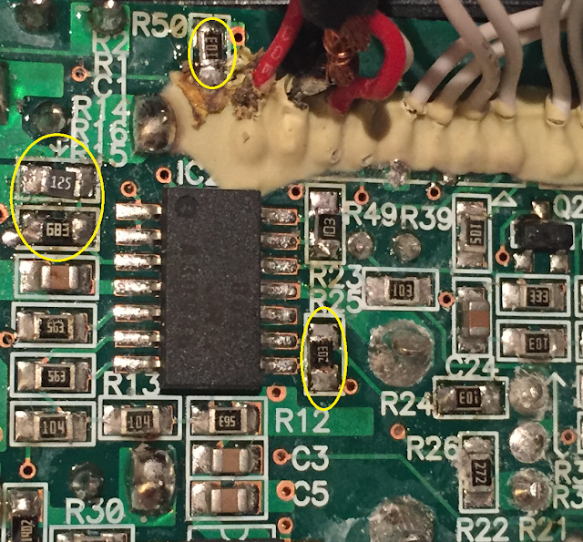
NOTE:
FOR a More robust voltage gain factor (3):
R25 30k (Or 33K standard value)
R24 10K
R49 20K
R50 10K
Enjoy
:-)
KK
Donate
https://www.paypal.me/kkprince999
Subscribe to:
Posts (Atom)